

🧱 Create Brick Molds
As mentioned earlier in Thinking in Semio,
A Type is your brick mold 🧱 The Blueprint behind each Brick
It defines not just the shape, but also the design meaning and connection logic 🔧
🧩 What Are the “Molds” in This Example?
Take a look at your sketch 👀
You’ll see five elements that follow the same basic shape, just stretched to different lengths 📏
Even though the final Design includes five Pieces, they’re made from only three distinct shapes
with two of them used twice — giving us three Variants of one Type 🔢
🧱 Think of it like a LEGO brick that comes in 2-stud, 4-stud, and 5-stud versions —
same shape logic, just scaled 📐
If the shape were completely different — like a triangle, window, or roof ⛰️🪟🏠
That would count as a new Type altogether
🧠 Modeling with Meaning
When you think of a mold, the first thing that comes to mind is usually its shape — the geometry 🧱✏️
But in Semio, the mold is what combines shape with meaningful design information 💡
In traditional Grasshopper workflows, you’re modeling with raw data — points, curves, and surfaces without embedding design intent 🧬
You build logic around it, but that logic stays detached — abstract, custom, and often fragile.
In Semio, the mold connects geometry with design intent directly 🧠
You’re not referencing arbitrary geometry — you’re referencing relationships, roles, and rules 🧩
For example:
👉 Instead of saying “connect point (x, y, z) to Brep edge 23”
👉 You say “connect the door to the living room” 🛋️🚪
👉 Or in LEGO terms: ”🪟 snap the window brick onto the top of the wall” 🧱
This is what gives Semio its strength — you’re not just building shapes,
you’re building a semantic system that adapts, scales, and speaks your design language 🎯🗣️
🧰 Create a Brick Mold (Type – Ty)
Let’s begin by modeling the mold shown in the sketch
This will serve as the base for generating its Variants 🧩
Before we start building, let’s go over the essential elements that define a Type 🧱:
- 🏷️ Name → A unique name to identify your Type and reuse it in different designs
- 🧱 Geometry (Representation) → The 3D shape attached to the Type — it gives the piece its visual form ✨
- 🧲 Connection Points (Ports) → The snap points where the piece connects to others in the system 🔗
Now let’s take a closer look at how these elements come together — and start modeling our first brick mold 🛠️
🏷️ Name Your Mold (Type Name - Na)
Clear, consistent names in Semio make everything easier down the line ✅
Especially when your project grows and you’re working with many Types, Variants, and Pieces 🔄Good names help you:
- 🧭 Navigate your system
- 🔍 Understand relationships
- 🔗 Make connections that are easy to track
👉 In our example, we’ll name our Type “Profile”
because the shape we’re modeling is based on a standard manufactured wood profile 🪵🧊 Attach Geometry (Representation – Rp)
In Semio, the process of adding geometry to a Type is called modeling its Representation 🛠️ A Representation is anything that visually or symbolically represents a Type 🧱 It helps you see or recognize the Type — without defining its logic or behavior 🧠
In most cases, this will be a 3D geometry, like in our example But it can also be:
- A 2D drawing or diagram ✏️
- A symbolic icon or block 🔳
- A label, file, or reference 🔖
💡 Because Representations are separate from the logic of the system, they’re fully flexible:
- You can start modeling your system without one 🚧
- You can add or update it later 🛠️
- You can switch between levels of detail depending on the design phase 🔍
In this example, we’ll use a simple 3D shape to represent our brick molds we need to create 🧩
🔧 Modeling Representation
There are two simple steps to create a Representation:
-
🛠️ Build the Geometry
Model the physical form of your brick — the shape that will appear in your design -
📎 Link it to the Type
Connect the geometry to a specific Type, so Semio knows how to display and use it in your design space
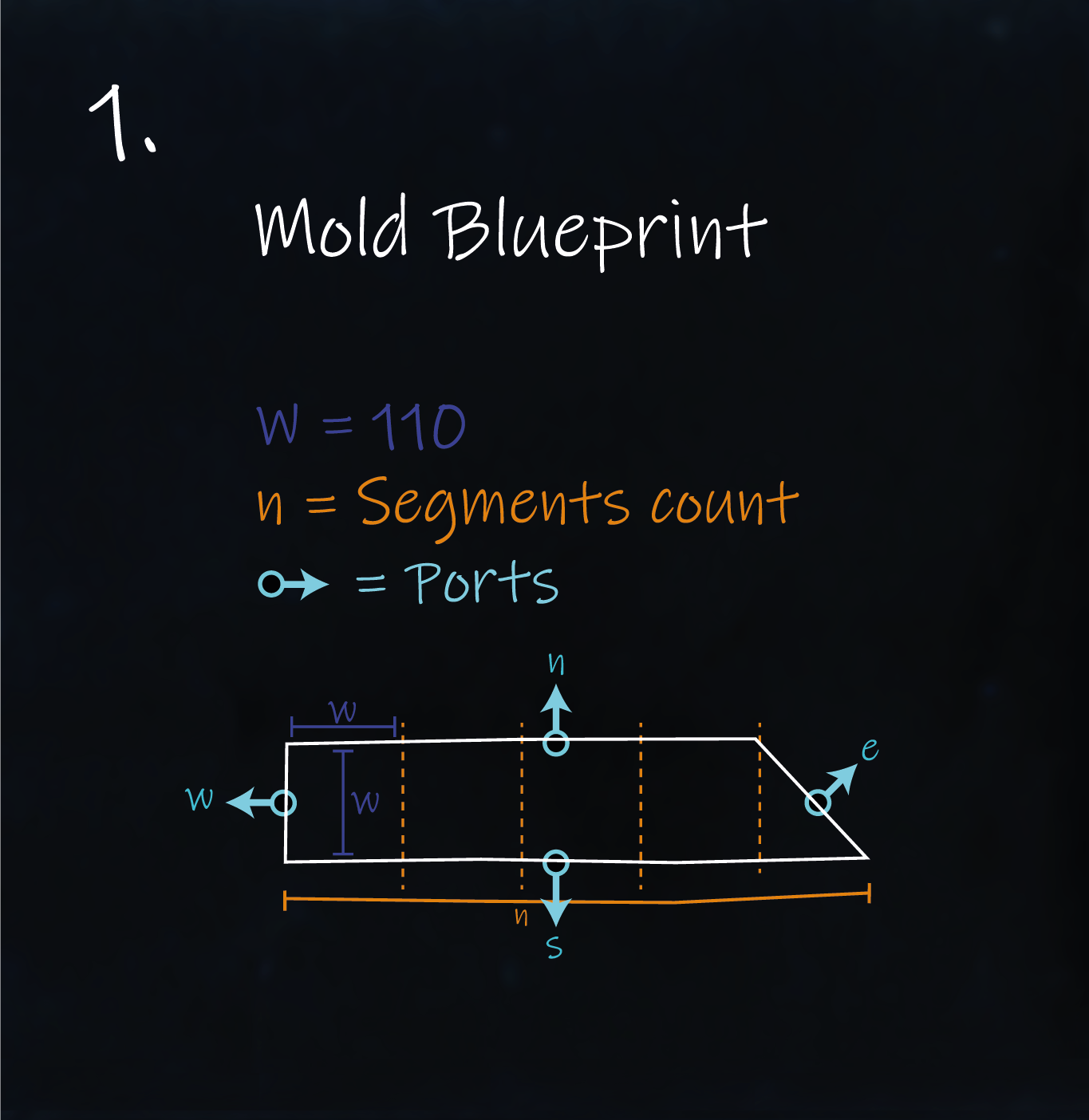
Let’s take a closer look at the brick mold in our example 👀
It always follows the same basic shape 🧱
A rectangle that’s cut at an angle ✂️ — just repeated in different lengths 📏As we saw in the sketch, its size is described using two parameters:
W→ the width of one brick unitn→ the number of units in length
In Semio, you can attach geometry to a Type in different ways 🔄
You can pick the method that best fits your workflow or tool.Let’s take a look at how that works in practice 👇
In Semio, Representations are typically referenced through external geometry files 🗂️
— even when those files are generated inside GrasshopperThis approach keeps your workflow clean, modular, and easy to update 🧼
It also makes your design system more reusable and scalable 🔁While the modeling process itself isn’t the focus of this tutorial,
here’s the key takeaway:
You’ll need to follow three simple steps to attach your geometry as a Representation 🧱🛠️ Geometry Modeling
Since our shape follows a clear logic 🧠
we use a parametric Grasshopper definition to generate the geometry of the brick mold 🧱This is useful because it lets us generate all the different Variants of this brick seen in the sketch
using a single logic controlled by the parametersnandW
which define the brick’s length and width 📏
💾 Geometry Export
After generating the geometry,
we need to export it as a.glbfile so it can be attached as a Representation 💾We’ll use a simple workflow that automates this export 🦾
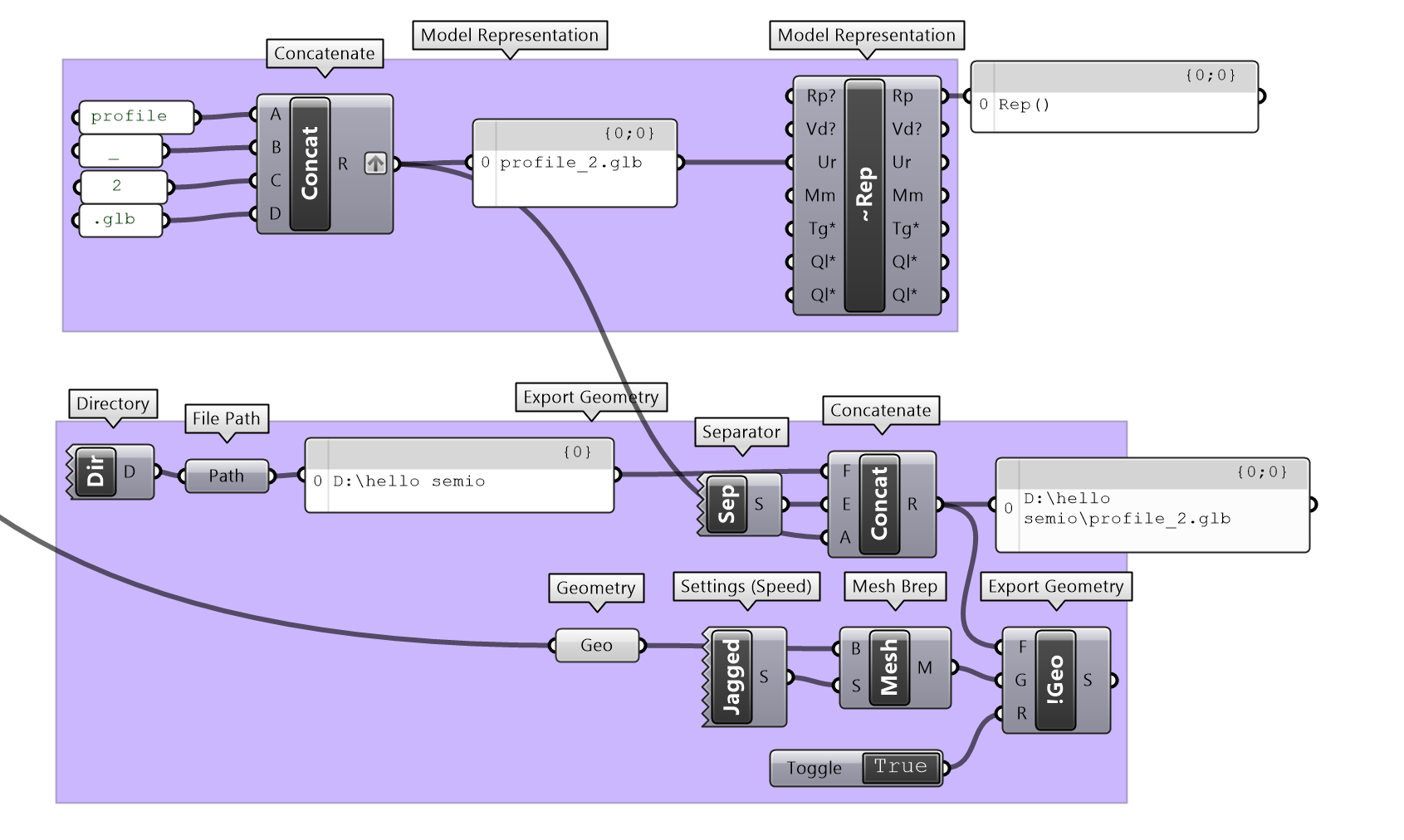
You can place it directly after your geometry generation step in Grasshopper 🦗🔁 The Export Workflow Looks Like This:
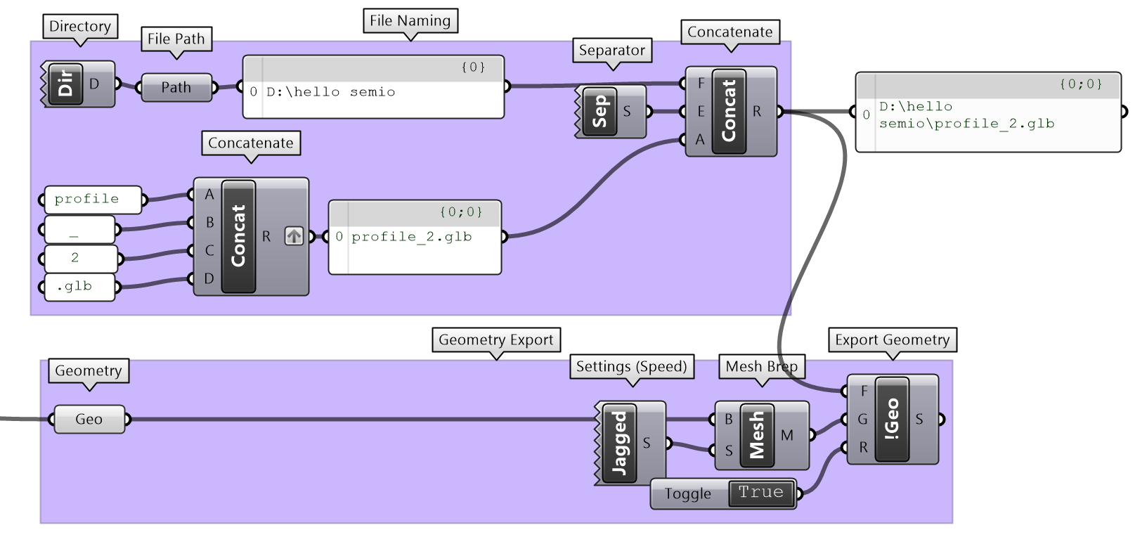
🗂️ Set the Export Location
Use the
DirandPathcomponents to define the directory path
This determines where the exported file will be saved📝 Build the File Name
Use
Concatto generate the file name dynamically
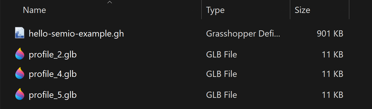
Combine the Type name and Variant (e.g.profile+2) →profile_2.glb🧩 Assemble the Full File Path
Another
Concatmerges directory + file name:
C:\Users\Users\Downloads\profile_2.glb📐 Prepare the Geometry
🛠️ You’ve already modeled the geometry earlier in your Grasshopper definition.
Now it’s time to export it — so Semio can use it as a referenced Representation 💾- ✅ Convert the geometry into the required format (e.g. Mesh for
.glb) - 📤 Pass it into the
iGeocomponent to export it as a.glbfile
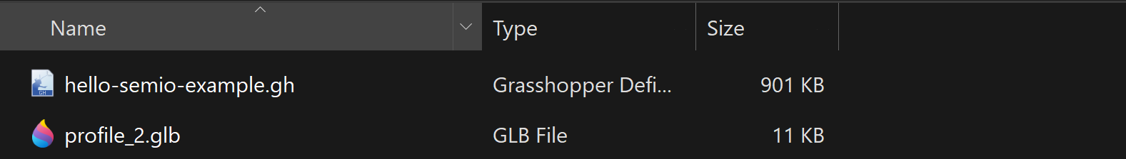
Your file directory should now look like this:
🔗 Referencing the Exported File
The exported file (e.g.
profile_2.glb) is linked to theUrinput of the Model Representation component (~Rep)
This tells Semio where to find the geometry that represents your Type.-
🧩 The
~Rep(Model Representation) component takes theUrfile path and creates a Representation:
→Rep(model/gltf-binary) -
🔗 This Representation is later connected to the
Typ(Model Type) component —
so that your Type is linked to its visual form
🔁 Why Use File-Based Referencing?
Even inside Grasshopper, Semio requires a file-based snapshot of your geometry —
a static file that captures what your brick mold looks like at a specific moment.Here’s why that matters:
- ⚙️ If your geometry is dynamic or parametric, it still needs to be exported to a file
- 🔗 Semio connects to that file — not the live Grasshopper preview
💡 This keeps geometry modular, portable, and easy to reuse
🧱 It also supports chunking — breaking down large designs into smaller, manageable parts
🌐 And it allows smooth transition between Grasshopper and Semio SketchpadYou don’t always need to embed geometry directly into a Type 🧱 In some cases, you can skip integration and reference the geometry directly in Grasshopper instead 🎛️
Just pass the geometry — either as a Geometry 🧊 or Object 🧩 — straight into the Preview Design component 👀 This lets you visualize your Design using custom shapes without embedding them into the Type’s definition 🔍
👉 We’ll explore this option in a later step. ⚠️ Just note: this method is for visualization only — the geometry won’t be part of the mold itself
🧪 Switching the Representation
As introduced earlier, when you give a Type its shape in Semio, you’re attaching a Representation —
a piece of geometry that shows what the brick looks like visually 👁️But this geometry isn’t fixed — it acts more like a placeholder 🧠
That means you can change or swap the Representation at any time without breaking your design logic 🔁You can think of it like a costume for your Type 🎭
The name, role, and connections stay the same — you’re just changing how it looks on stage 🎬This flexibility is especially useful when working across different levels of detail in a project 🧩
Just like architects might use blocky volumes for urban massing 🏙️
and detailed profiles for close-ups or fabrication 🪟
Semio lets you swap the look without changing the logic 🔄
Same brick — different shell 💡🎬 One Brick, various Representations
To illustrate this concept, we created two geometry files for the same brick mold Type:
This version uses the fully detailed geometry of the piece 🪵
A rectangle cut at an angle and extruded into a realistic wooden profile ✏️
It includes every visible detail in 3D: full depth, edges, and joinery-ready shapes 🔍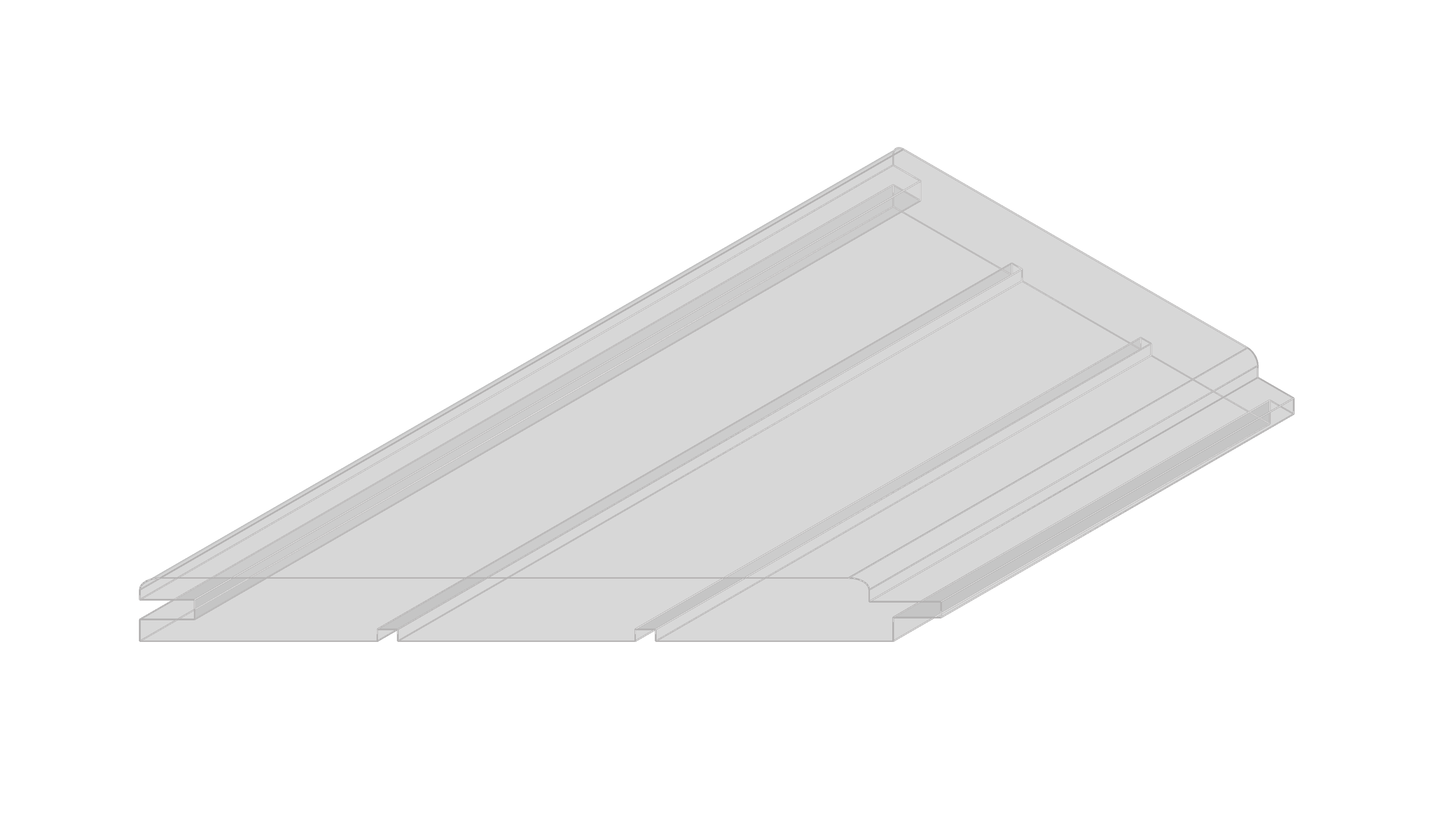

Best for:
- 🪚 Joinery and production planning
- 📐 Material-specific outputs
- 🖼️ Detailed documentation and renders
This version is a flat sheet simplification 📄
A single-surface geometry that represents the general size of the piece 📐
It captures only one dimension and skips all 3D detail 🚫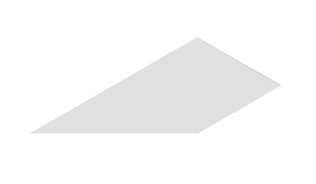

Use this when:
- 📐 Only the 2D footprint is known
- ✏️ The full shape is not finalized yet
- ⚡ You need fast previews or early-stage coordination
This version is a bounding box simplification 📦
A simple block that approximates the piece’s volume ➕
It includes two dimensions but omits exact geometry 🧊
Best for:
- 🧪 Early-stage layouts and feasibility checks
- ⚙️ Quick iterations and high-speed previews
- 🧊 Placeholder geometry before final detailing
Even though these two Representations look very different
They both belong to the same Type ✅The Name, Variant, Ports, and logic stay exactly the same
Only the appearance changes 🎭This means you can design and assemble everything using lightweight placeholders 🧩
Then swap in the detailed version when you’re ready for presentation, communication, or fabrication 🧰This separation of logic and form is what makes Semio workflows flexible, scalable, and robust 🔄
From early concept to detailed design to collaborative development 🤝⚓ Add Snapping Points (Ports - Po)
Once your brick mold has a visual shape — its Representation —
the next step is to define how it connects to other bricksThat’s what Ports are for 🧲
They act as snap points that tell Semio where and how a brick can attach to others🧩 What Do You Need to Define a Port?
In the Semio Grasshopper plugin, each Port is defined with three main inputs:
-
🏷️ Port ID (
Id)
A unique name for the Port — like a tag or label used to connect it later
Examples:"n","bottom","hingePoint" -
📍 Point (
Pt)
The exact spot where the connection happens — like placing a stud on a LEGO brick 🧱
You place this carefully on your geometry, right where the snapping should occur -
➡️ Vector (
Dr)
The direction the Port faces — telling Semio which way the brick will connect 🔁
It’s what lets Semio rotate and align the bricks correctly when snapping them together
📍 Port Location (
Pt)When modeling Ports, it’s not just about where pieces touch —
it’s about building a clear and reusable logic that works across all Variants 🧠🔁Here’s how to define your Ports effectively:
-
🧱 Choose stable, meaningful locations
Choose positions that are geometrically logical — like the center of a face, an edge midpoint, or a corner 🧩
Avoid placing them randomly — symmetry and regular patterns help your logic stay clean ♻️ -
📐 Keep positions consistent across Variants
Even if your bricks differ in size or shape, place Ports in the same relative location 🔄
This way, your connection rules stay valid across all versions of a Type 🧰 -
🎯 Don’t worry about perfect alignment
Ports don’t need to be exactly placed.
Semio lets you adjust each Piece’s position and rotation after snapping 🛠️
So prioritize clear logic over micrometer precision 😌
There’s no strict rule for how many Ports to add — it depends on how much flexibility your system requires:
- 🔒 Fewer Ports → simpler, more controlled snapping
- 🔓 More Ports → more layout options and greater orientation flexibility
- 🧠 Plan ahead → add Ports you might need later, even if they’re not used right away
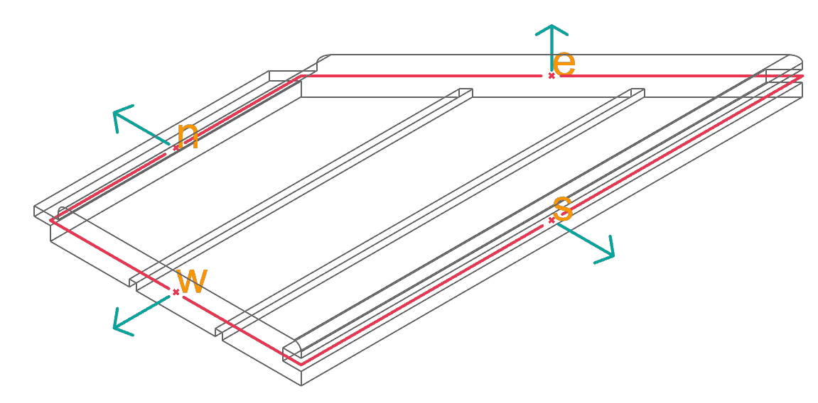
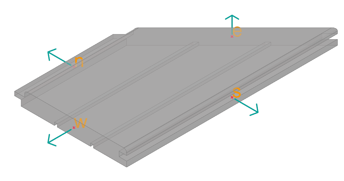
👉 In our example, we place four Ports — one at the center of each edge of a four-sided profile 🧱
💡 Port Direction (Dr)
Every Port needs a direction — a vector that tells Semio which way the connection should face 🧭
This is how Semio knows how to align and snap your Pieces together correctly 🧲Here’s how to define Port directions clearly:
-
📏 Use clean, simple vectors
Stick to basic axes like X, Y, or Z relative to the face the Port sits on. It makes snapping easier and logic more readable 🧠
Avoid random or diagonal directions unless needed -
♻️ Be consistent across Variants
Ports don’t need to be perfectly precise — but they must stay consistent
This ensures all your bricks connect correctly no matter the shape or version 🔧
👉 In our example, each Port faces straight out — perpendicular to the edge it’s placed on 🚀
🏷️ Port ID (Id)
A Port ID is the name you give to each Port 🏷️
This name is how Semio knows which Port to connect when snapping Pieces togetherFor example, you might say:
“Connect the
topPort of Piece A to thebottomPort of Piece B”You can use any naming system — as long as it’s clear and consistent:
- Common examples:
n,s,e,w— for north, south, east, and west 🧭 - Custom names:
top,bottom,hinge,plug,windowDock, etc. 🧲
💡 Tip: Pick a naming system that’s easy to understand and stick to it
It helps you stay organized and makes teamwork or AI assistance much easier 🤝Together with the Pt (position) and Dr (direction), the Id completes each Port definition:
Each row in the three lists defines one Port — so all lists must be the same length to stay in sync 🧩Now you can see how the three inputs — Id, Pt, and Dr — work together to create Ports. Each Port is defined by one entry from each list, so the lists must be the same length. This ensures that every snapping point has a matching ID, position, and direction
-
🧱 Assemble the Mold (Model Type)
Once you’ve defined all parts of your brick mold
the Name, Variant, Ports, and Representation
you can assemble them using theModel Typecomponent (Typ) 🧰Here’s what you plug in:
- 🏷️ Name — the shared identity of the mold (e.g.
"Profile") - 🔢 Variant — the specific version number (e.g.
"2") - 🧲 Ports — the snapping points and directions (e.g.
n,s,e,w) - 🧊 Representation — the geometry that defines the brick’s shape
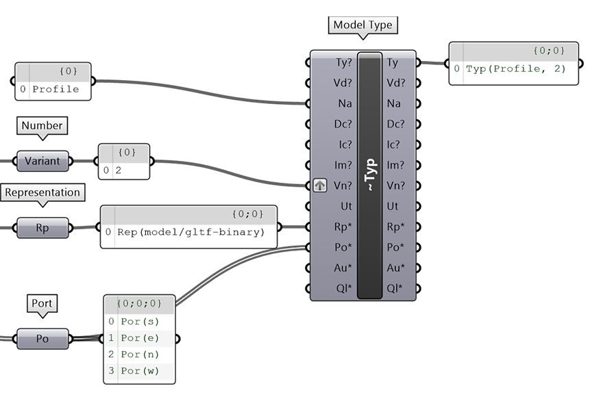
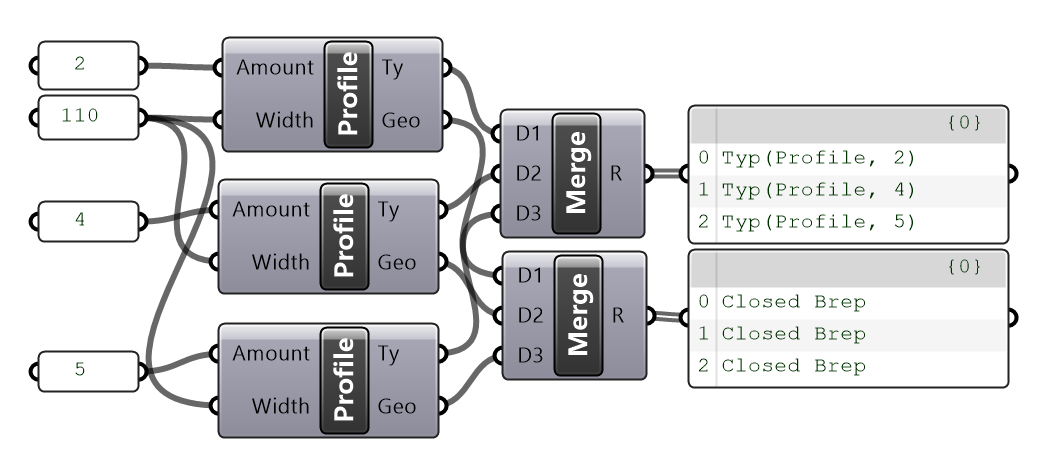
🎯 The result is a complete Type
A reusable brick mold that carries both shape and connection logicFor example,
Typ("Profile", 2)
creates Variant2of the"Profile"mold
a 2-unit-long brick ready to be placed in your Design 🧱- 🏷️ Name — the shared identity of the mold (e.g.
🧬 Create Mold Versions (Variants of Type)
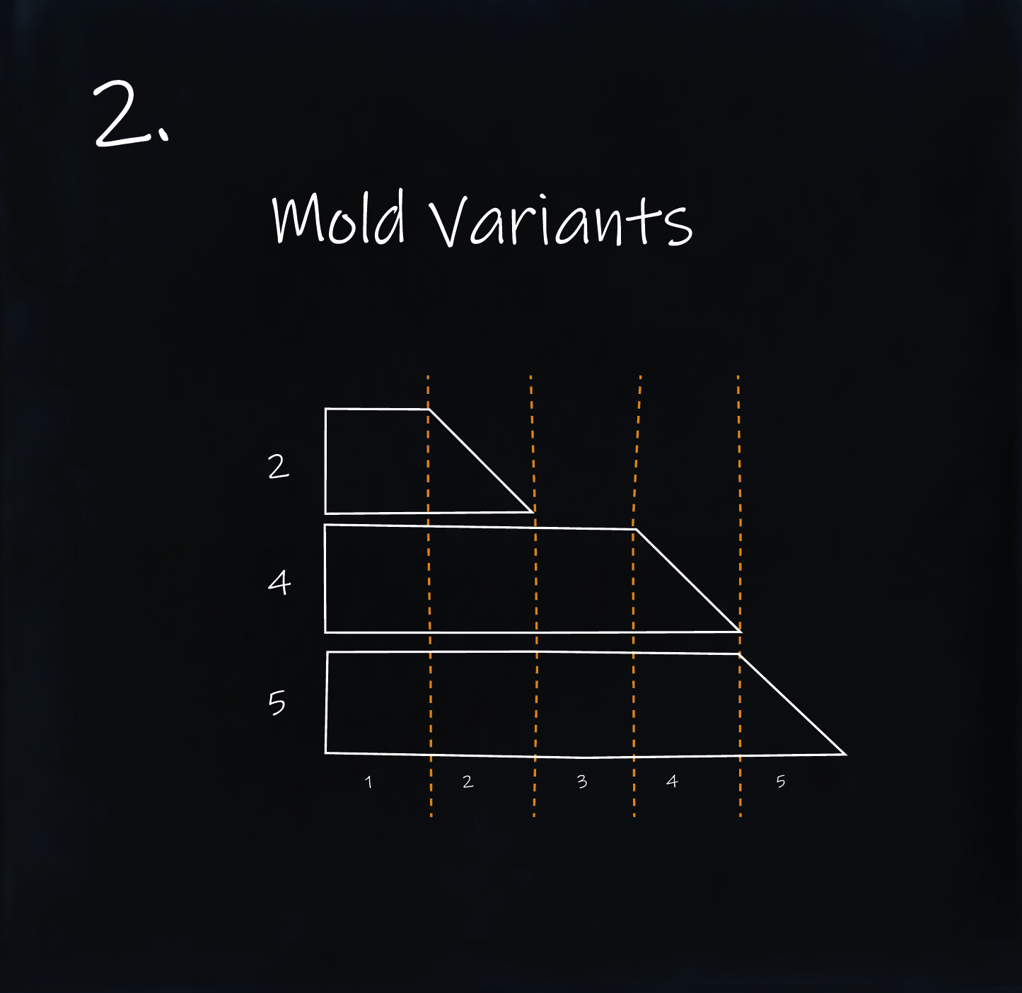
Now that you’ve created your base Type, it’s time to generate Variants — based on the unit count n shown in the sketch 🔢
Each Variant is built from the same mold, just stretched or scaled to a different length 📏
Think of it like longer or shorter LEGO bricks of the same kind 🧱
Since they follow the same logic and structure, we treat them as Variants of one Type — not separate Types ♻️
Examples from our sketch:
Variant 2→ 2 units long 🟩🟩Variant 4→ 4 units long 🟩🟩🟩🟩Variant 5→ 5 units long 🟩🟩🟩🟩🟩
🔁 Modeling a Variant
✅ What Stays the Same
- 🏷️ Type name — you’re still using the same underlying mold
🔄 What Changes?
- 🔢 Variant name — a unique label like
2,4, or5to distinguish the version - 🧊 Representation — new geometry that reflects the Variant’s shape or size
- 🧲 Ports — same logic, but positioned relative to the new shape
🛠️ Modeling Steps
- 🏷️ Set the Type name (same as the original mold)
- 🔢 Assign a new Variant name
- 🧊 Attach the Representation — the geometry for this Variant
- 🧲 Add the Ports — positioned consistently
- 🧱 Use the
Model Typecomponent to combine everything into a complete Variant
✅ That’s it — same mold, new shape, fully ready for modular design
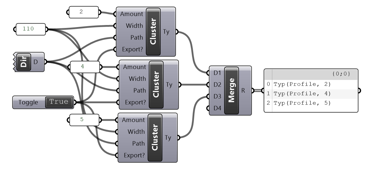
💡 Advanced Tip: Use Clusters to Generate Variants
In Grasshopper, a great way to handle multiple Variants is with a Cluster
Since most Variants share the same logic and differ by only one or two parameters, a Cluster helps you:
- 🔁 Model the logic once
- ⚡ Generate all Variants efficiently
- 🧼 Keep your script clean and modular
Inside the Cluster:
You define the full logic:
- 🧊 Generate and export geometry
- 📎 Link the exported file via
Model Representation - 🧲 Place Ports using
Model Port - 🧱 Create the Variant using
Model Type
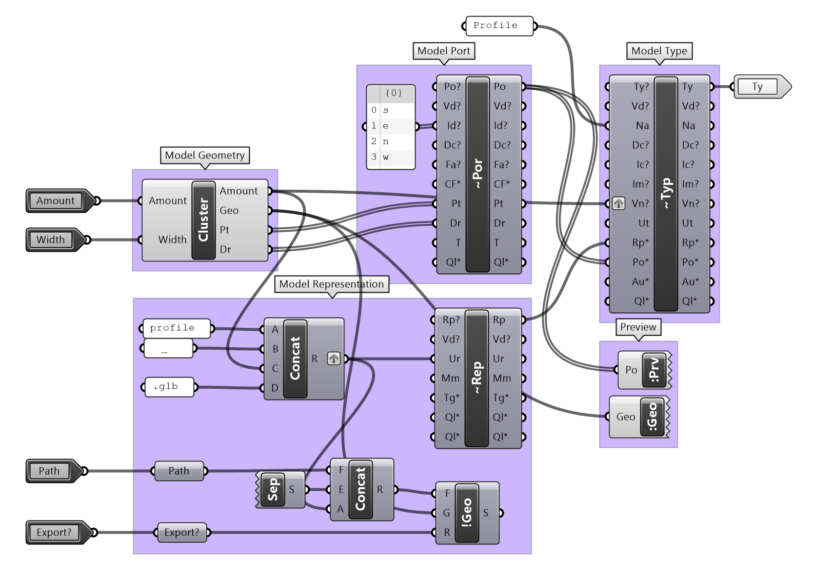
Outside the Cluster:
You only feed in the changing inputs:
- 📏
n→ the unit count (e.g. 2, 4, 5) - 🏷️ Variant name → often also
n - 📁 Directory of the GH file
- 🔘 Export toggle
Inside the Cluster:
You define the full modeling logic directly, without saving external files:
- 🧊 Generate geometry
- 🧲 Place Ports using
Model Port - 🧱 Create the Variant using
Model Type
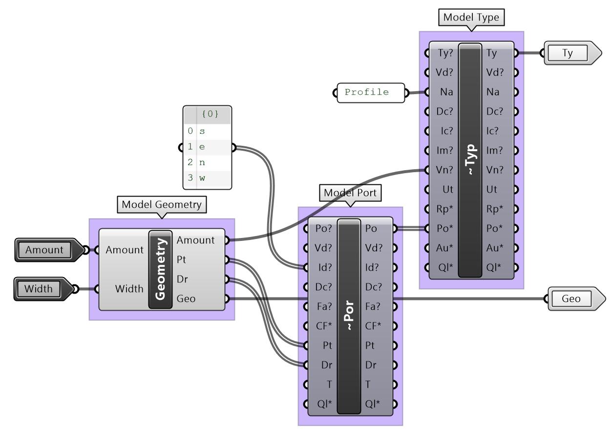
Outside the Cluster:
Only the changing parameters are connected:
- 📏
n→ the unit count (e.g. 2, 4, 5) - 🏷️ Variant name → often also
n
✅ Bonus: This workflow keeps your file organized, scalable, and easy to expand — perfect for growing your Kit later on 🧩