

🧩 Create Design
This section shows how to turn your brick molds — the Types and Variants you’ve defined — into real, usable building blocks 🧱
As explained in [Think in Semio], a Type is just a blueprint. It defines how a brick should look and behave — but it’s not a brick yet 📐
To actually build a design, you need to create Pieces — the bricks made from your molds, ready to place, connect, and assemble 🧩
🔖 Place Your Bricks (Model Pieces – Pcs)
Now it’s time to turn your molds into actual bricks — called Pieces 🧩
These are the elements you’ll place, move, and connect in your design 🎯
When you create a Piece, you’re telling Semio:
“Take this specific mold (Type + Variant) and make a real, usable brick from it.” 🧱
Each Piece automatically includes everything from its mold:
- Geometry (Representation) — the shape defined by the Variant’s geometry file 🧱
- Ports — the snap points and their directions from the Type ⚓
- Semantic Data — the Type name, Variant identity, and design role 🧠
- Metadata — any extra info like function, material, or tags 📄
In short: a Piece is a fully formed brick, based on the rules and shape you defined earlier 🔁
🆔 Name the Pieces
Each Piece needs a unique name — its ID — so Semio can 🧭 track, 🔗 reference, and 🧩 connect it later on. Think of it as giving your brick a personal label 🏷️
In this example, we name the Pieces based on the Semio logo — using both color and position for clarity 🎨
- 🟨
Yel→ yellow piece on the left - 🔴
Red-T→ red piece at the top - 🔴
Red-R→ red piece on the right - 🔵
Blu-T→ blue piece at the top - 🔵
Blu-B→ blue piece at the bottom
As always in Semio, naming is flexible 🔤
But a clear and consistent system makes your design easier to understand, build, and share 🧠
💡 It’s like putting a sticker on each LEGO brick so you always know which one goes where 🧱
🧬 Link to the Mold
To model a Piece, Semio needs to know which mold it’s made from 🔗
That means linking it to a specific Type and Variant:
- 🏷️ Type name → e.g.
'Profile' - 🔢 Variant number → e.g.
2,4, or5
👉 Without this reference, the Piece has no identity — it won’t know what shape to take or how to connect ⚠️
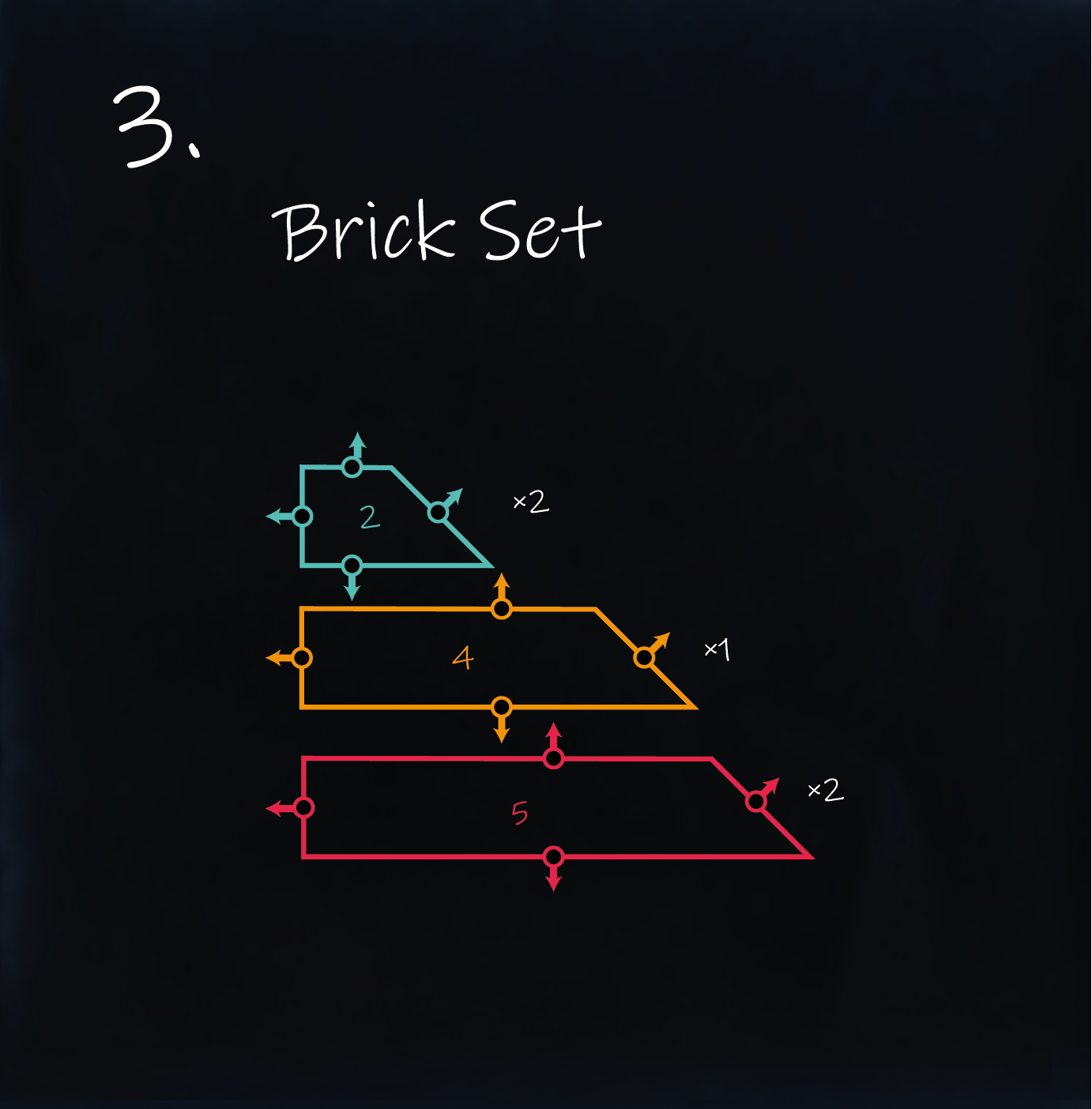
📐 Example from the Sketch
In our example, the final Design includes five Pieces, built from three different Variants:
- 2× Variant
2 - 1× Variant
4 - 2× Variant
5
We’ll give each of these Pieces a unique ID, like so:
| Variant | Piece IDs |
|---|---|
4 | Yel |
5 | Red-T, Red-R |
2 | Blu-T, Blu-B |
These are the actual bricks you’ll be placing into your model 🧱
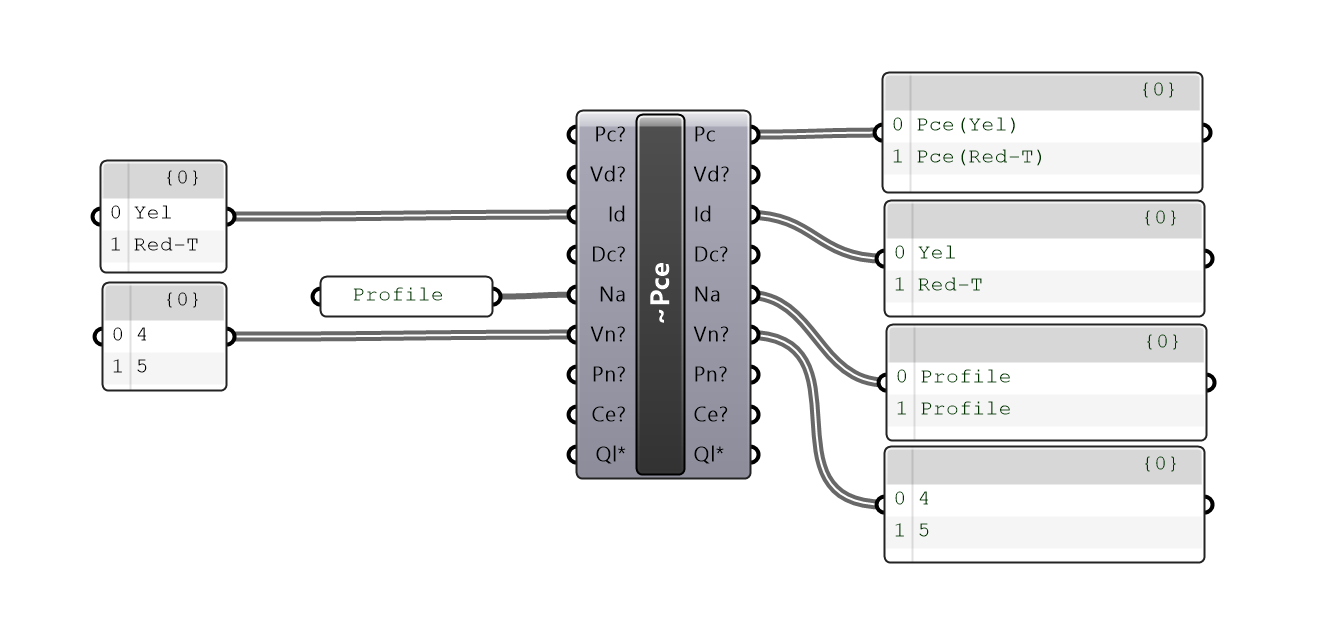
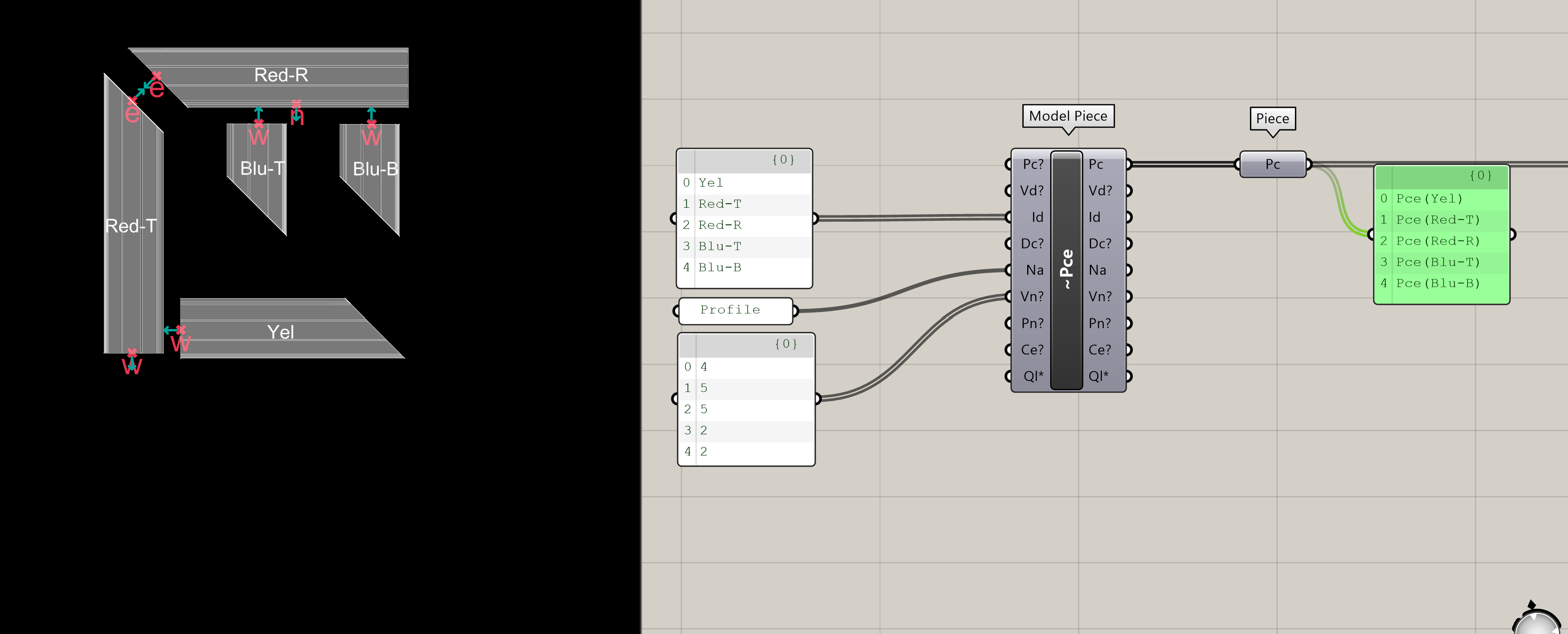
🛠️ In Grasshopper
Now that you understand what a Piece is, let’s learn how to cast them using the Semio plugin in Grasshopper 🦗
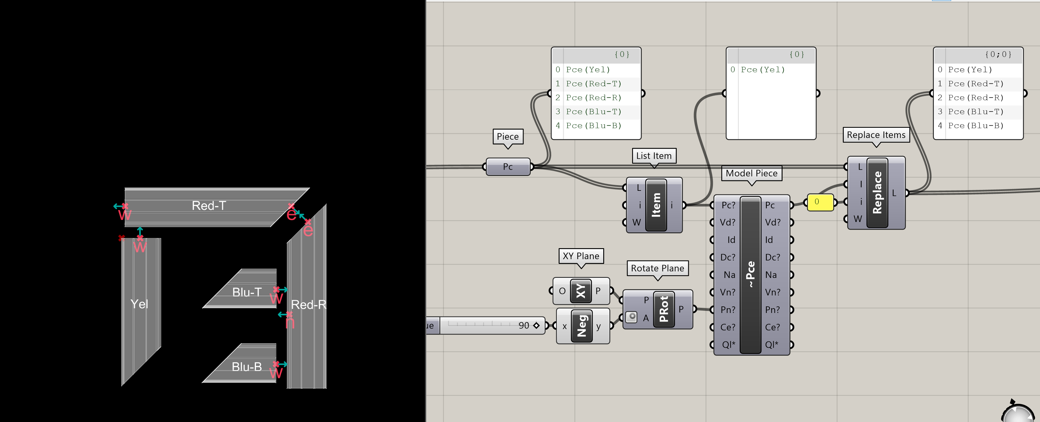
As shown in the image, you’ll use the Model Piece Pce component and provide three key inputs:
- 🆔 Piece IDs → Unique names for each brick (e.g.
Yel,Blu-B) - 🔢 Variant Numbers → Tell Semio which Variant of the mold to use (e.g.
2,5) - 🏷️ Type Name → The shared name of the mold (e.g.
'Profile')
Each row becomes a new Piece, named by its ID — like Pce(Yel) or Pce(Red-R) —
each one inherits geometry, ports, and semantic logic from its Type and Variant 🔁
🧱 Let’s start by modeling the first two Pieces from the sketch
Once all five Pieces are created, your model will look like this:
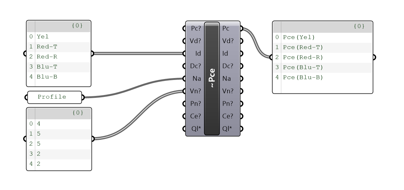
✅ Your bricks are now cast and ready
Next step: placing and connecting them to build your final model 🔗
🔗 Connect the Bricks (Model Connections - Con)
Now that you’ve placed your Pieces, it’s time to tell Semio how they connect 🔗
Think of this like writing the assembly instructions for snapping bricks together 🧲
Each Connection says:
👉 “Connect this Port on one Piece to a Port on another Piece”
🧭 Set the Connection
To create a connection, you need to define four values:
- 🆔 Connected Piece ID (
CdPc) → the Piece you’re connecting from - ⚓ Connected Piece Port ID (
CdPo) → the Port you’re connecting from - 🆔 Connecting Piece ID (
CgPc) → the Piece you’re connecting to - ⚓ Connecting Piece Port ID (
CgPo) → the Port you’re connecting to
Put simply:
➡️ Connect this Port on this Piece → to that Port on that Piece
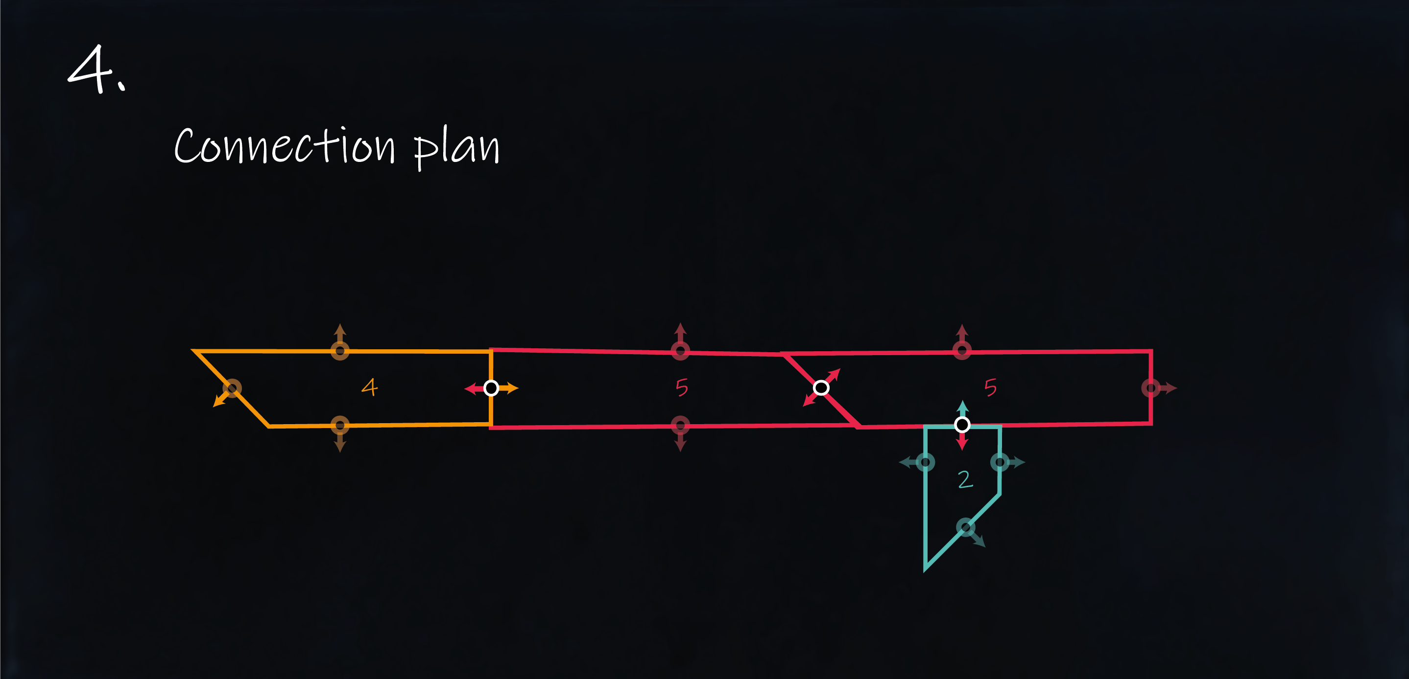
🧩 Example: Connecting Two Pieces
🧱 Before snapping the full model together, let’s start small — by connecting the first two bricks.
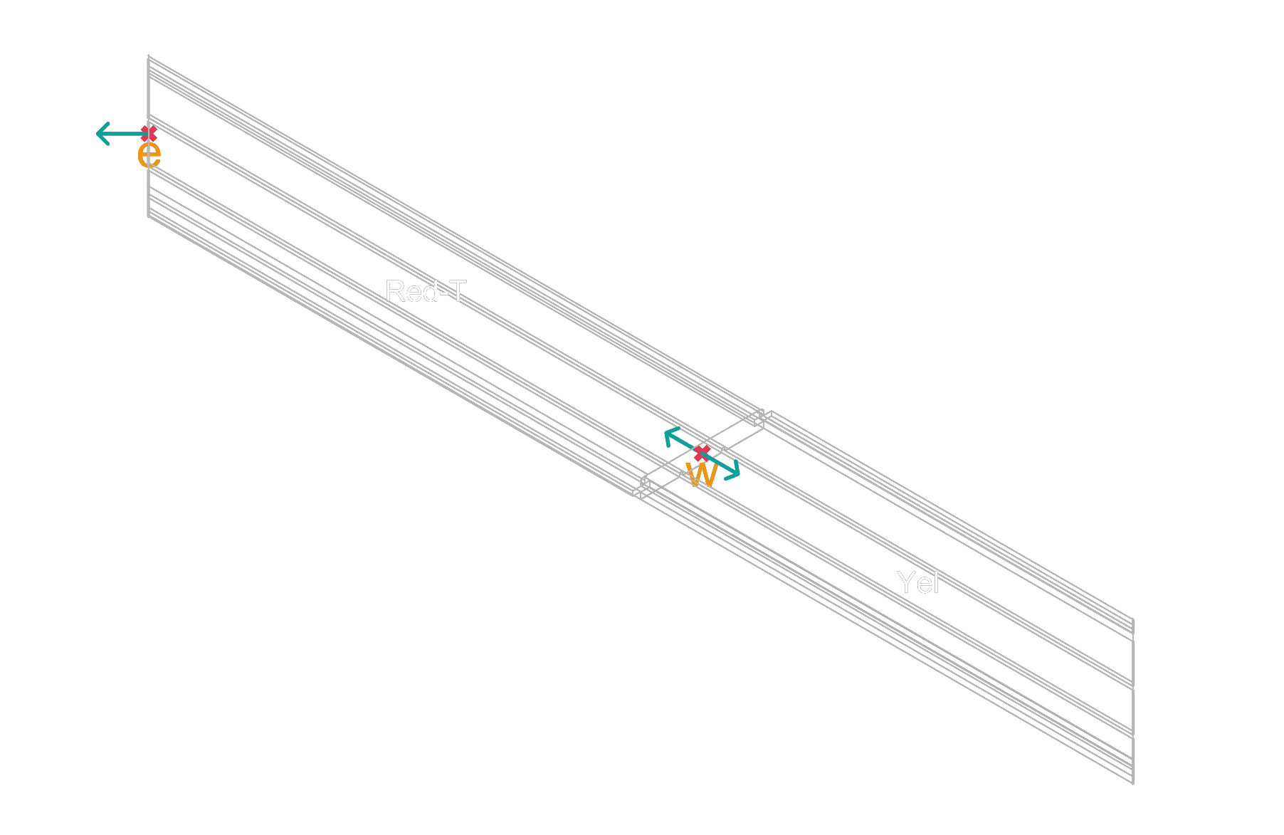
We’ll connect Piece Yel to Piece Red-T, using their west-facing Ports.
From the sketch, we can tell:
- Use the
w(west) Port ofYel - Connect it to the
w(west) Port ofRed-T
So the connection looks like this:
Con(Yel:w → Red-T:w)
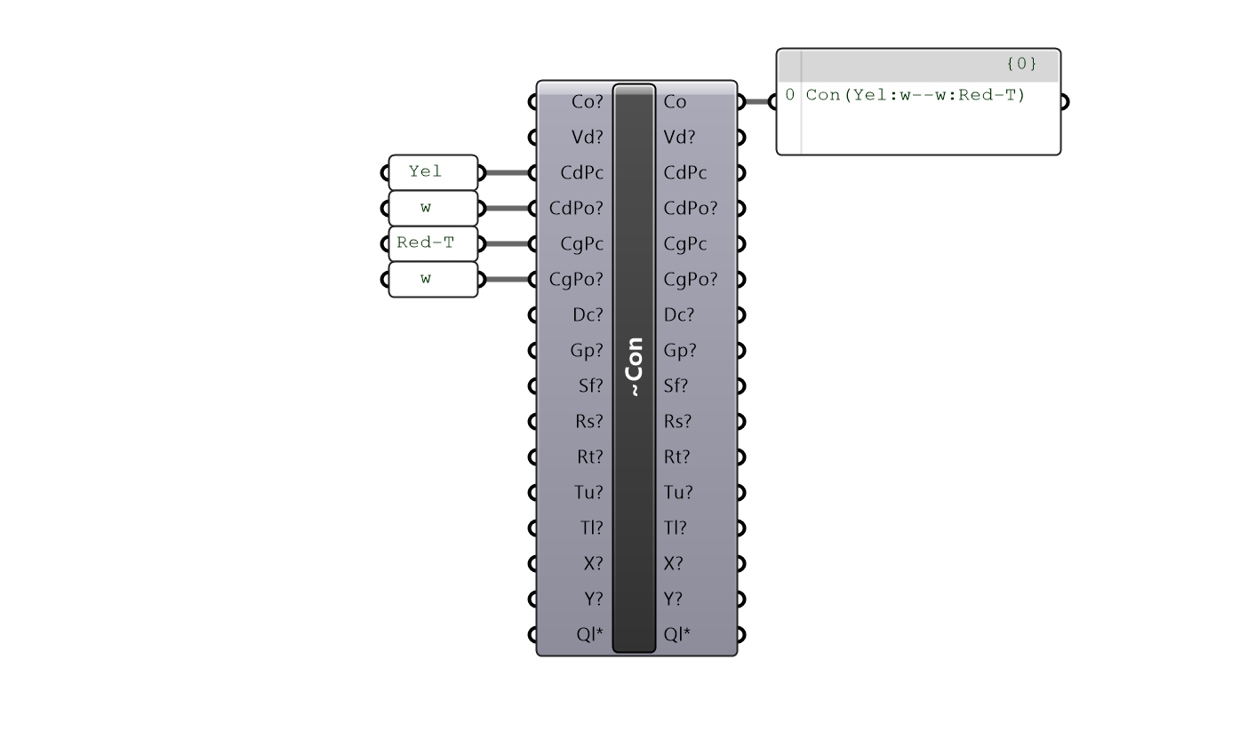
This tells Semio:
Snap the west Port of Yel to the west Port of Red-T
Once this first connection is in place, you can continue snapping all remaining bricks together using similar logic 🧩
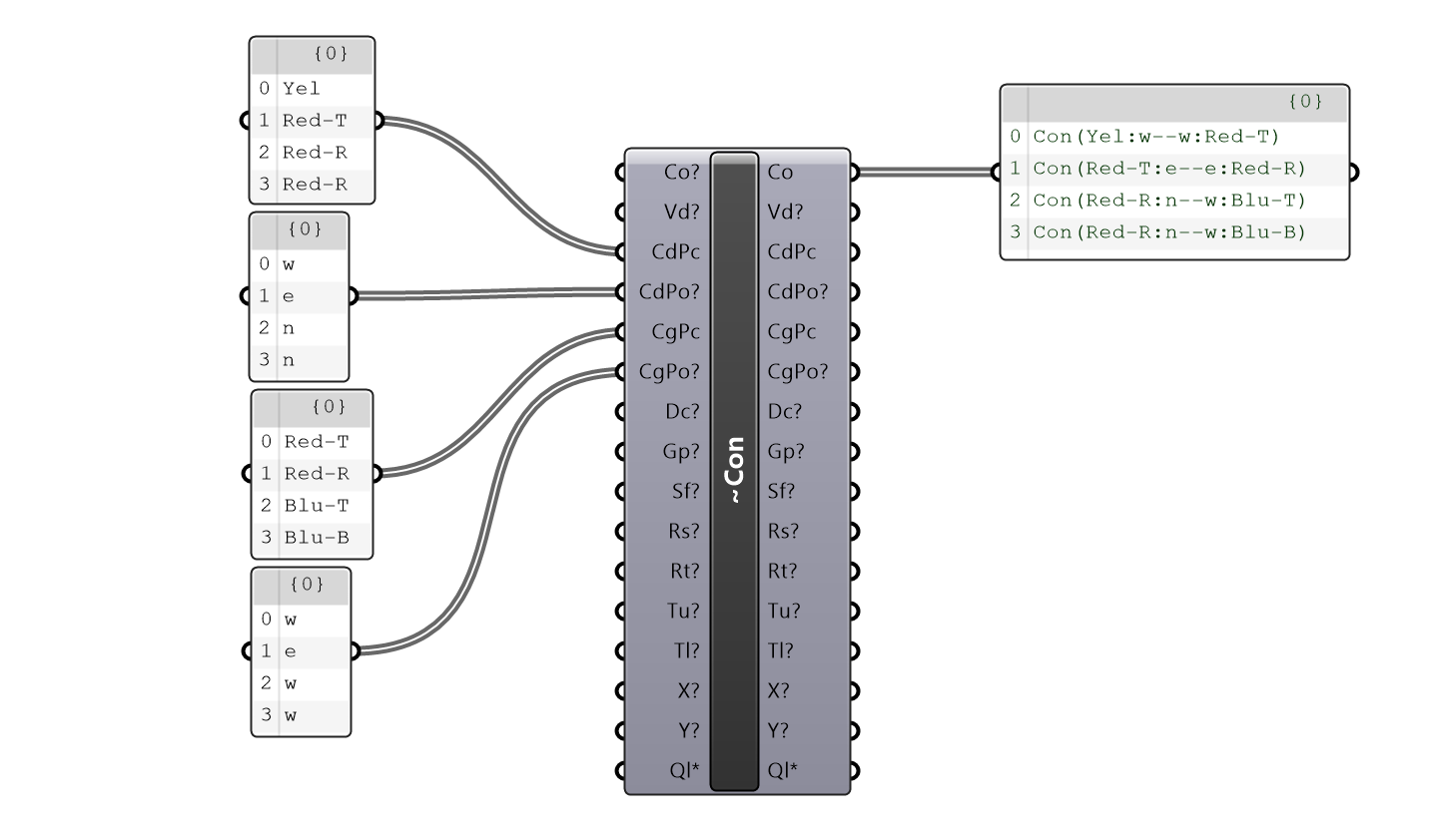
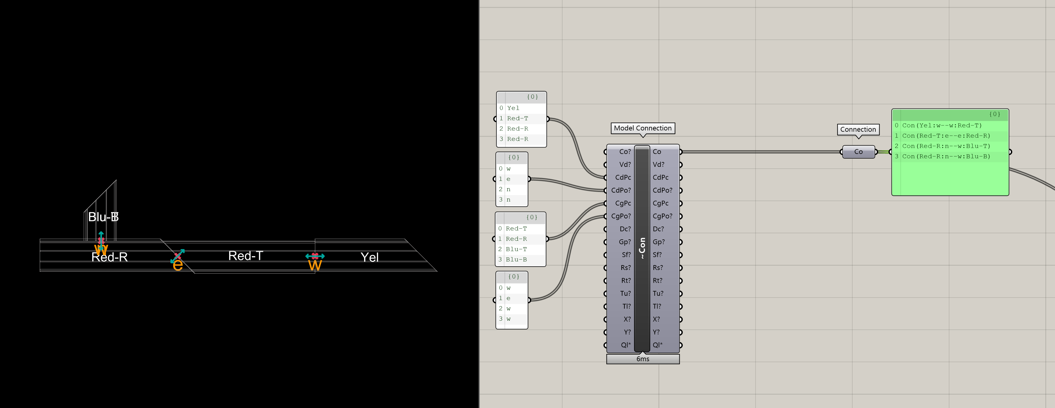
🔗 This Tells Semio:
-
Con(Yel:w → w:Red-T)
👉 Snap the west Port ofYelto the west Port ofRed-T -
Con(Red-T:e → e:Red-R)
👉 Snap the east Port ofRed-Tto the east Port ofRed-R -
Con(Red-R:n → w:Blu-T)
👉 Snap the north Port ofRed-Rto the west Port ofBlu-T -
Con(Red-R:n → w:Blu-B)
👉 Snap the north Port ofRed-Rto the west Port ofBlu-B
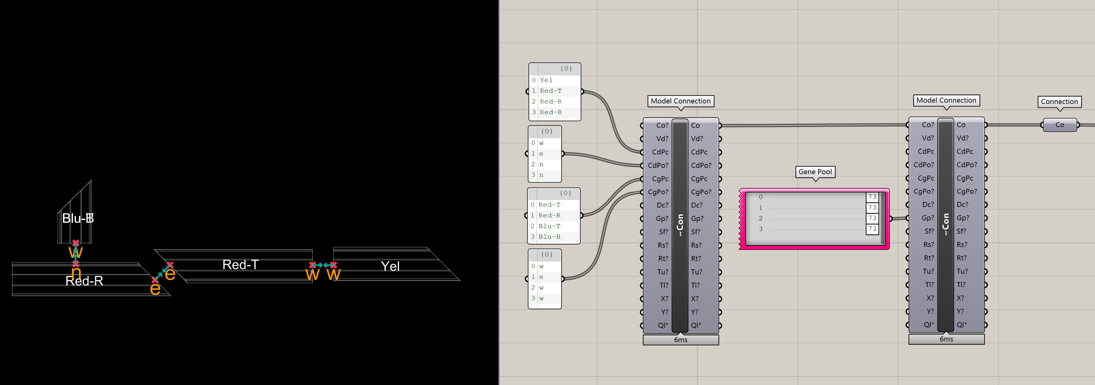
🎯 Adjust Snap (Optional Step)
When two Pieces are connected through Ports, Semio gives you control over how the attached geometry is positioned —
without changing the Port itself.
These adjustments are applied relative to the orientation of the Port, based on how it was defined in the mold (Type).
📌 Use this when the geometry needs to be slightly offset — to float, shift, or align more precisely.
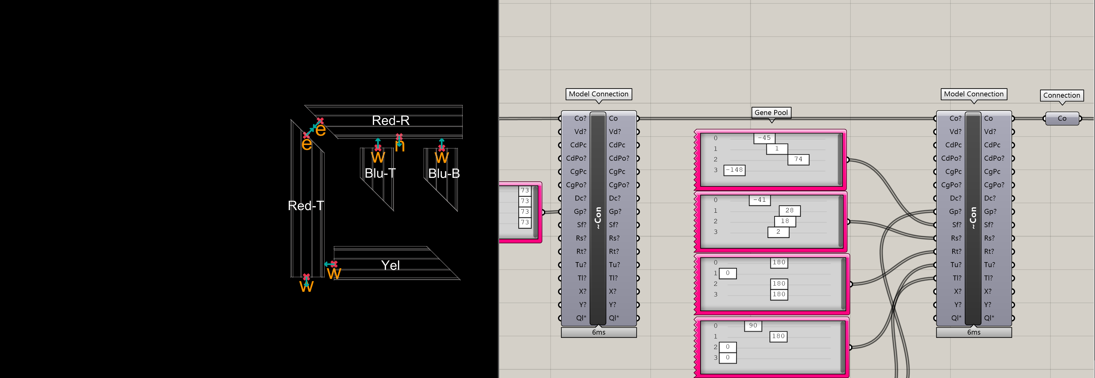
🔁 Move (Translation)
You can move the geometry in three local directions:
-
Gap ⬅️➡️ → Creates a space between two connected elements by pushing the Piece forward or backward along the Port’s axis Ideal for separating elements or creating breathing room between parts
-
Shift ↔️ → Moves the Piece side to side, across the plane of the Port
📐 Like nudging a LEGO brick left or right to line it up with studs underneath -
Raise ⬆️⬇️ → Lifts or lowers the Piece vertically, perpendicular to the face it connects to
🪜 Like lifting a brick slightly higher or lowering it onto the studs
🔄 Rotating (Orientation)
-
Rotate 🔃 → Rotates the Piece flat, around the Port’s main vector 🧭 Like spinning a round LEGO tile in place
-
Turn 🔄 → Turns the Piece sideways, rotating it horizontally 🌀 Like twisting a LEGO hinge side to side
-
Tilt 🤸 → Tilts the Piece forward or backward, around a vertical axis 🎢 Like tilting a ramp or slope brick up or down
As we can see, the two Pieces we connected earlier don’t align exactly as shown in the sketch 🧩
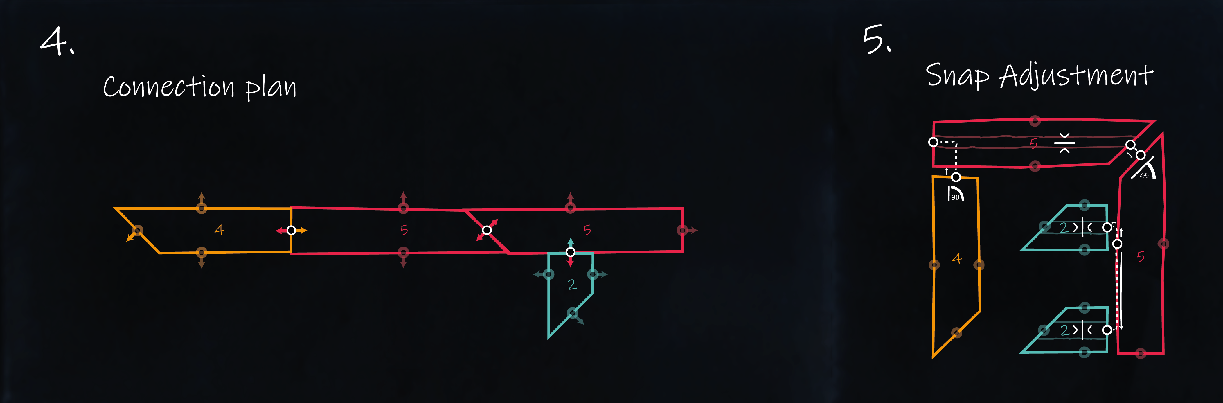
This is where the optional step of adjusting the snap comes in 🛠️
Semio lets you fine-tune the position of a connected Piece after snapping 🧲
You’re not changing the Port itself ⚓
Instead, you’re offsetting the geometry that comes with it 📐
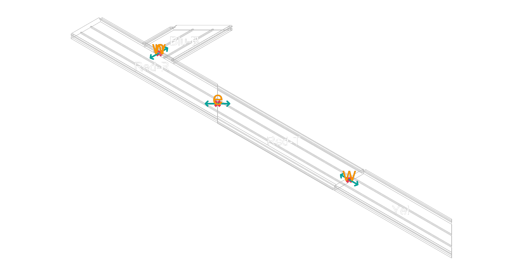
➕ Connecting the Rest of the Pieces
Once i and L1 are correctly aligned ➡️
you can continue connecting the remaining Pieces one by one ➕
📌 Just follow the sketch:
Each new Piece is snapped to the previous one using their matching Ports ⚓
— and adjusted as needed to match the layout.
🌀 If a connected Piece isn’t facing the right way,
you can rotate it individually — Semio allows per-piece rotation without breaking the connection logic 🔄
🔗 And thanks to Semio’s chain behavior,
when you move or rotate one Piece, all the connected Pieces after it will update automatically 💫
🏗️ Build the Design (Model Design - Dsn)
Now that you’ve created your Pieces and defined their Connections, it’s time to bring them all together into a final Design 🧰
🧩 What is a Design?
A Design in Semio is your full model — created by snapping together specific Pieces 🧱 using their Connections 🔗
It doesn’t just describe geometry 👁️ — it defines how each part fits, aligns, and works within the system 🧠
You’re building not just a shape, but a smart, modular structure 🧬
🧱 Think of it like a finished LEGO build:
You’re not just stacking bricks — you’re creating a model where every part has a role 🎭, a position 📍, and a purpose 🎯
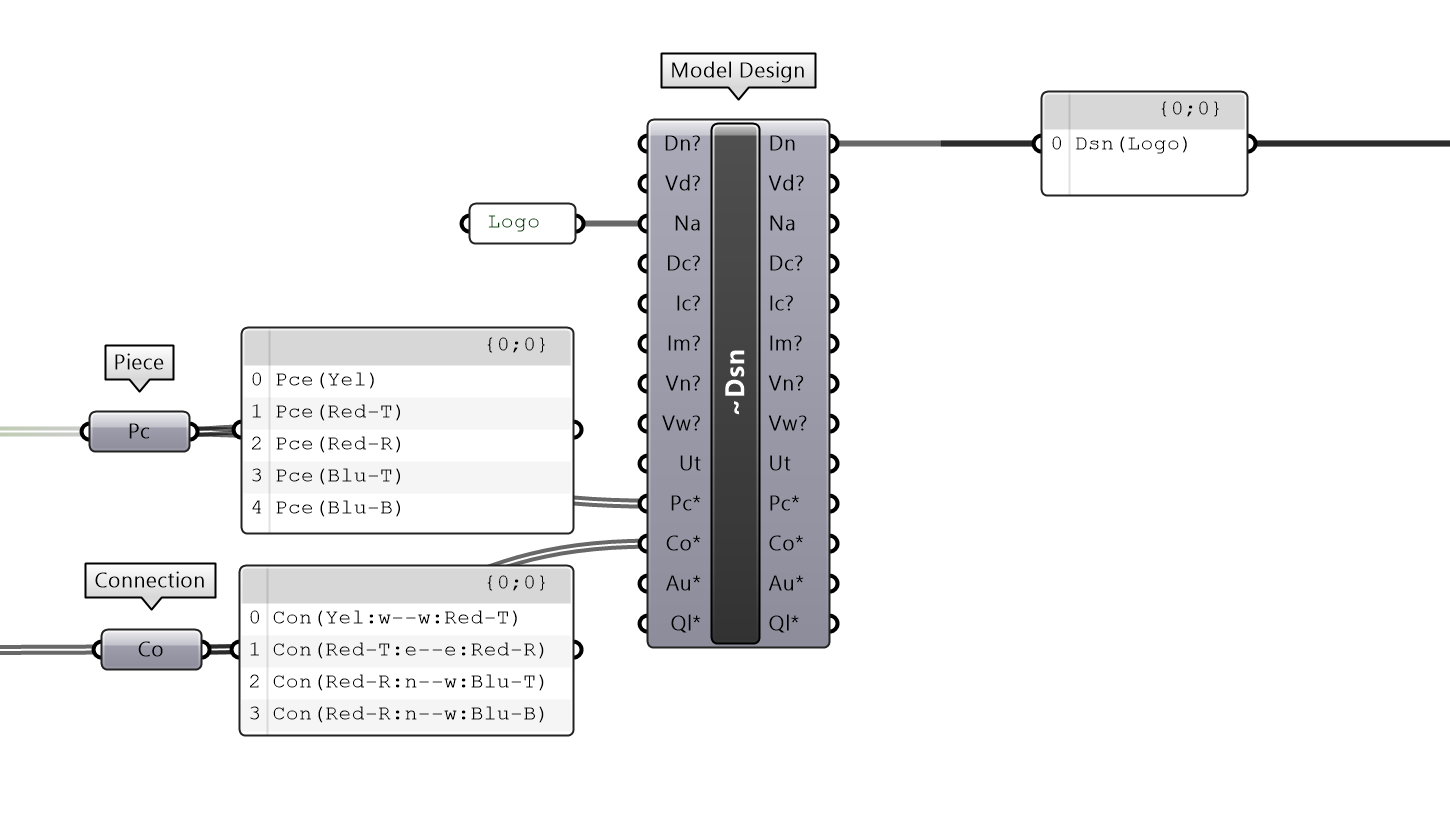
🛠️ Assembling the Design
To build your Design in Semio (e.g. in Grasshopper), you’ll use the Model Design component.
This is where you bring together all the Pieces and Connections to form your complete model 🧩
You’ll provide three main inputs:
-
Design Name (
Dn) 🏷️
A unique name for your model — like"Logo Example"or"Spaceship". -
Pieces (
Pcs) 🧱
A list of the Pieces you’ve created — each one linked to a Type, Variant, and unique ID. -
Connections (
Con) 🔗
A list of the snapping rules — telling Semio how the Pieces are connected through their Ports.
Example:
⚙️ Workflow Mechanics
Now that we’ve covered the core concepts of Semio, let’s take a closer look at how the components actually work —
and explore the key features of the Semio workflow inside Grasshopper
🛠️ Grasshopper Workflow
Semio doesn’t change how Grasshopper works — it changes what you’re working with.
You’re no longer just wiring geometry — you’re wiring design intent 💡
- Types 🧱 – Brick molds with meaning, not just shapes
- Pieces 🧩 – Placed bricks that follow system logic
- Connections 🔗 – Rules that control how elements relate
- Designs 🧰 – Full assemblies of smart, connected pieces
This shift lets you create not just geometry — but structured, adaptable systems 🧠
Semio components behave just like regular Grasshopper components 🧩
- 📋 You still work with lists and data trees
- 🔢 Items are matched by index or branch
Want to set a gap ⬅️➡️ or a rotation 🔁?
Just provide a matching list of values — each one applies to the corresponding item in your list of Connections or Pieces.
🔄 Contruct, Deconstruct, Reconstruct
In Semio, Model components like Model Type, Model Piece, Model Connection, and Model Design follow a shared logic:
they’re not just builders — they’re also editors and inspectors.
Each component supports three fundamental actions:
1. 🔨 Construct
Each Model component can create a structured Semio object from your inputs:
Model Type→ outputs aTy(Type)Model Piece→ outputs aPc(Piece)Model Connection→ outputs aCn(Connection)Model Design→ outputs aDs(Design)
These are Semio’s core data types — they carry geometry, logic, metadata, and relationships.
2. 🔍 Deconstruct
You can also use the same component to inspect or extract the inner structure of a Semio object, and all its inputs will populate with the current values, like unpacking a brick to see how it was made.
3. 🔁 Reconstruct / Modify
In Semio, you can update any modeled object — like a Type, Piece, Connection, or Design —
by feeding its output back into the first input of the same Model component.
Ty→ Type 🧱Pc→ Piece 🧩Cn→ Connection 🔗Ds→ Design 🧰
When you do this, you can redefine any part of the object (like its name, geometry, plane, or metadata).
Only the inputs you change will be updated — everything else stays exactly as it was
🧪 Example Use Case
🧩 Modify a Piece
You can modify any aspect of a Piece — such as its name, placement, or other construction parameters by feeding its Pc output back into a new Model Piece component 🧩
Semio will only override the inputs you change — everything else stays exactly the same 🎯
E.g. In the “Hello Semio” logo example, rotating the first Piece flips all connected Pieces as well — because they’re linked logically
_
🔗 Adjust a Connection
You can adjust any transformation or rotation parameters of a Connection by
plugging the Cn output back into a new Model Connection component 🔁
Semio will only update the values you change — all other settings will remain as they were 🔒
This makes it easy to fine-tune how two Pieces are connected without rebuilding the whole logic 🔧
E.g. You can change the gap, shift, or rotation of an existing Connection, and all downstream geometry will update automatically.
🧱 Update a Type
You can update a Type by feeding its Ty output back into the same Model Type component 🔁
This lets you modify its Representation, Ports, or metadata — without changing anything else.
E.g. Swapping a simplified geometry file for a detailed one, or updating tags like material or category.
🧰 Refactor a Design
To modify a full Design, feed its Ds output into a new Model Design component 🔁
You can update the Design name, reorganize the structure, or tweak how certain Pieces are connected.
E.g. Renaming a layout, replacing a few bricks, or adjusting a connection — without touching the rest.
🖼️ What Happens Next?
To see your model, plug everything into the Preview Design component 👀
It displays all your Pieces in place — fully connected, correctly oriented, and ready to go 🧱